
Dust collector purging system problem – blowing pipe design
When Zonel Filtech helps clients to improve their dust collectors, some of them complained that the purging systems of their bag filter housing do not work well even if they use the air leading pipe on the air blowing pipe, with the venturi, and also with a correct pressure for the compressed air, so they cannot find the solution to improving the purging works.
After analyzing their purging system, the Zonel engineers found the main reason is that the distance between their air-leading pipe to bag tube sheet was not correct. If the distance is too big, the air may blow some to the bag tube sheet instead of into the filter bags; on the contrary, if too small, the pressed air cannot lead enough air outside into the filter bags, and the purging effect sure won’t be good.
But how to define this distance (H1 in the following drawing) ?
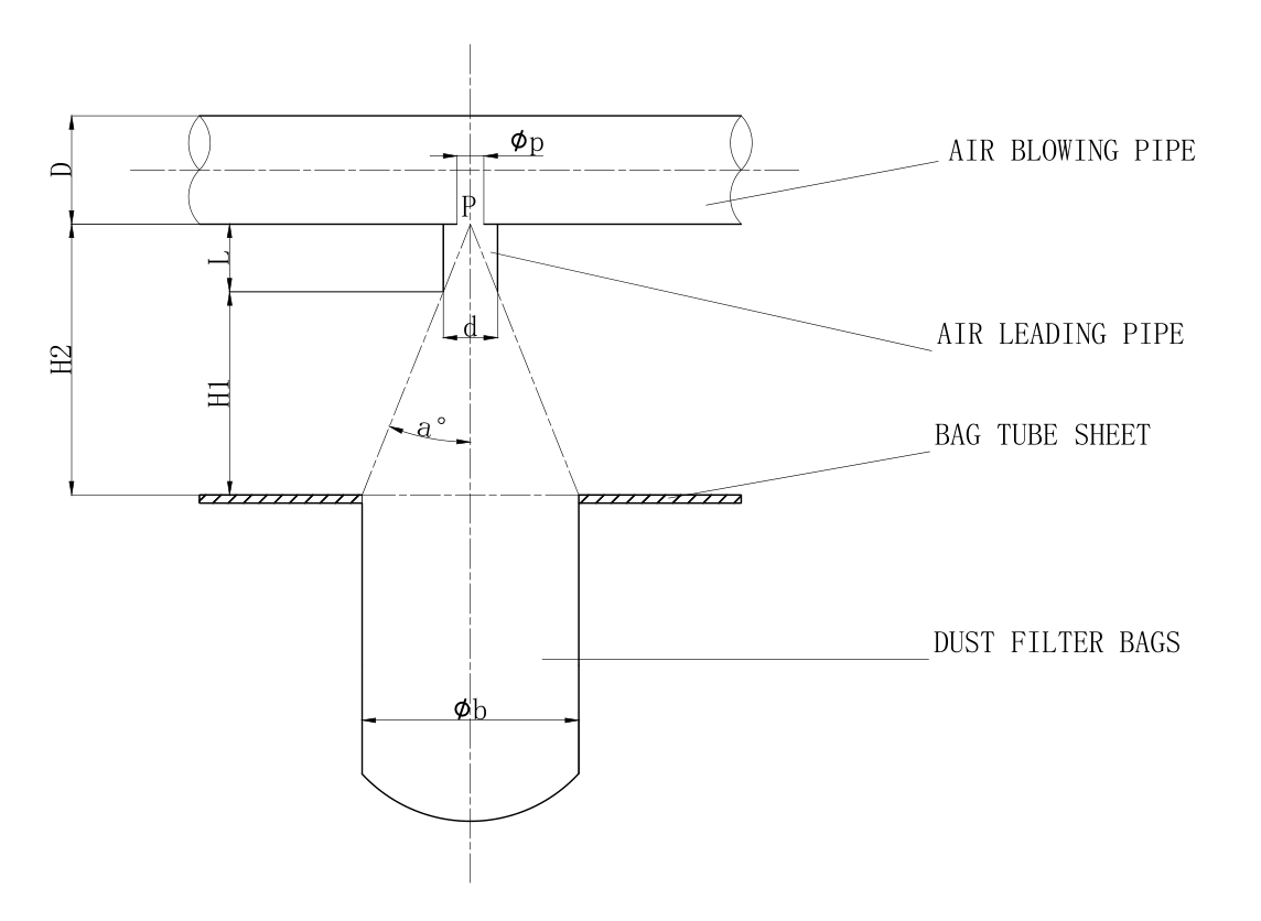
1. First step, you need to define the average value of the Øp in the drawing.
As usual, we calculate the Øp with the following formula:
Øp=(C*D^2/n) ^1/2
C=Coefficient, as usual, choose 50%~65%.
D=pulse jet valve outlet diameter, as usual, the same as air blowing pipe.
n=the filter bag number per row (purging with the same pulse jet valve)
As usual, C we choose 0.55.
Mostly, the air-leading pipe diameter is 2~3 times the Øp.
2. Define the length of the air-leading pipe.
Air leading pipe as usual uses the following formula:
L=Ck* Øp/K
Ck=coefficient, as usual, choose 0.2~0.25
K=is jet turbulence coefficient, cylindrical chooses 0.076.
i.e. L= about 0.2* Øp/0.076=2.65 Øp
3. It’s very easy to get that tg a degree =(1/2 Øb)/H2
tg a degree= 3.4K=0.272 (can be treated as a constant)
So a degree is chosen 15 degrees.
For example:
If choose a 3” immerged pulse jet valve, leading pipe d=30mm, and filter bag diameter is 160mm, how to get H1?
Answer:
Obviously, the H1=H2-L
So we have to define the H2 and L.
tg a degree =(1/2 Øb)/H2=3.4K=0.272
i.e. H2=1.838 Øb
Øb = 160mm
So the H2=294 mm
3” as usual the average Øp=15 mm (also can calculate when the bag qty be offered, or according to the experience data, appended please find.)
From the previous result, L=2.65 Øp, so the L=2.65*15=40 mm
So the H1=294-40=254mm.
For the Qp, generally, the average data can be chosen as follows:
Pulse jet valve size —- Qp
3/4”—-5~7mm
1” —- 6~8mm
1 1/2”—-7~9mm
2”—-8~11mm
2 1/2”—-9~14mm
3”—-14~18mm
4”—-16~22mm
As usual, when the Qp design is divided into 3~4 groups, closer to the pulse jet valve, the open size bigger, and from group to group the diameter differences are about 1mm.