
Residual liquid in a filter housing is process fluid remaining after filtration stops and the vessel drains. Excessive retention complicates maintenance, increases handling requirements, and can cause product losses during filter replacement.
Reducing this volume requires attention to housing geometry, drain positioning, venting, piping, and filter element construction. Proper operating procedures and drawing-specific drainage requirements also influence achievable results.
What Causes Residual Liquid in a Filter Housing?
Gravity drainage depends on the relationship between the housing’s internal geometry, installation orientation, and drain connection position. Liquid cannot leave efficiently when collection points sit below the available outlet.
Flat internal surfaces, recessed areas, uneven transitions, and structural supports can create pockets where liquid remains after the main discharge stops. These areas may be difficult to identify from external inspection alone.
Housing configurations also influence drainage behavior. Single-side-in/bottom-out arrangements, top-in/bottom-out designs, multi-bag vessels, and cartridge housings have different internal flow paths and potential liquid-retaining areas.
When liquid leaves an enclosed vessel, replacement air must enter through an appropriate venting arrangement. Insufficient air admission can create negative pressure that slows or interrupts gravity drainage.
Not all retained liquid remains inside the housing chamber. Filter bags and cartridges can hold additional fluid within their media, seams, support structures, and internal passages.
Viscosity, surface tension, media construction, and filtration conditions influence how much liquid remains attached to or absorbed within the filter assembly. Therefore, an empty vessel does not necessarily mean dry filter elements.
Engineers should distinguish three retention locations: housing low pockets, filter media or cake, and connected piping deadlegs. Each requires a different assessment and corrective approach.
Optimize Filter Housing Structure for Effective Drainage
Different filter housing configurations require different drainage approaches, depending on their internal structures and connection arrangements. Understanding these differences helps engineers identify practical improvements before modifying existing equipment.
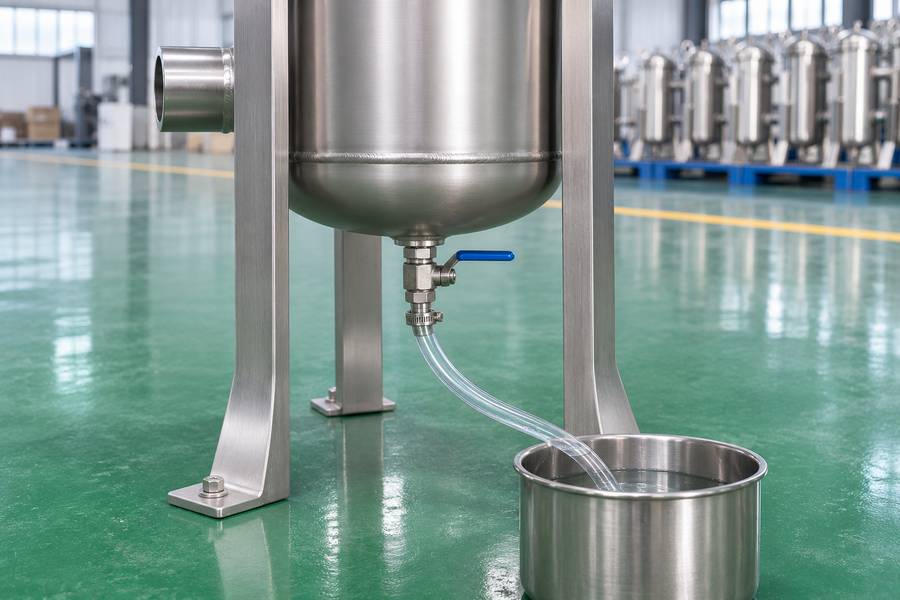
The drain connection should communicate with the lowest practical liquid collection point under the specified installation orientation. A connection located above an internal low point cannot remove the liquid below it through gravity alone.
Engineers should examine the bottom profile, internal connection geometry, and any structural components surrounding the drain opening. A nominal bottom drain does not automatically establish that every internal area can empty.
For housings containing separate upstream and downstream chambers, drainage requirements should be evaluated independently. Each chamber may require its own suitable drainage path, depending on the equipment configuration.
Installation level also matters. An incorrectly positioned vessel can create unintended low points that prevent liquid from reaching the designated drain connection.
Before installation, review the manufacturer’s drawings for the specified mounting direction, support arrangement, connection positions, and maintenance clearance. Avoid changing the equipment orientation without confirming its structural and operational suitability.
Internal components should support filtration without unnecessarily obstructing liquid movement. Basket supports, cartridge mounting structures, connection transitions, and reinforcement features deserve attention during design reviews.
However, removing or modifying internal supports must not compromise element positioning, pressure resistance, sealing, or filtration performance. Structural changes require appropriate engineering review rather than improvised modifications.
| Design factor | Potential retention problem | Engineering consideration |
| Drain position | Liquid collects below the outlet | Review the lowest practical collection point |
| Housing orientation | Incomplete gravity drainage | Confirm installation direction and level |
| Internal geometry | Liquid remains in recessed areas | Review pockets and drainage paths |
| Support structures | Liquid accumulates around components | Evaluate internal clearances and transitions |
| Chamber arrangement | Separate areas retain liquid | Assess individual chamber drainage |
Improve Venting and Piping to Support Liquid Removal
A suitable vent allows replacement air to enter as process liquid leaves the housing. Its location should reflect the internal chamber arrangement and the intended drainage direction.
Venting must also account for process hazards. Discharged vapor, hazardous liquid residues, and potentially contaminated gases require suitable routing and containment under the approved plant procedure.
Connected piping can retain liquid independently of the housing. Low points, unnecessary horizontal runs, deadlegs, and poorly positioned valves may prevent complete recovery even after the vessel has drained.
Where gravity drainage is intended, review pipe slopes, discharge elevations, and the receiving system’s pressure conditions. Restrictions or downstream backpressure can reduce the available driving force for liquid removal.
Gravity drainage may be insufficient for viscous liquids or installations with unavoidable elevation constraints. Engineered liquid displacement or recovery arrangements may provide an alternative when compatible with process requirements.
Gas displacement requires particular care. Only manufacturer-approved arrangements with engineered pressure controls, suitable pressure boundaries, and a compatible safe gas should be considered.
Never connect an arbitrary compressed-air supply to accelerate drainage. Uncontrolled pressurization can create serious hazards, introduce contamination, or exceed the equipment’s approved operating limits.
Establish a Proper Filter Housing Drainage Procedure
Stop the incoming liquid supply and isolate the housing using the designated valves. Confirm that connected equipment cannot introduce additional liquid through backflow or an unintended supply path.
Follow the approved depressurization procedure and verify the pressure boundary is safe before opening the housing. Consider process temperature, residual vapor, and the chemical properties of retained liquid.
Route vented material through the designated safe discharge system. Operators should never loosen covers, clamps, or connections to release trapped pressure or accelerate drainage.
Open the designated drain according to the approved operating sequence. Provide replacement air through the specified vent arrangement while collecting discharged liquid in an appropriate recovery or containment system.
Where product recovery matters, keep recovered usable product separate from cleaning waste and contaminated drainage. This distinction supports accurate material accounting and prevents unsuitable liquid from returning to the process.
Check accessible internal areas for remaining liquid before removing filter bags or cartridges. Inspect support structures and lower housing sections where liquid may collect outside the main drainage path.
Filter elements can release additional liquid during lifting and removal. Use suitable containment, handling equipment, and protective measures to prevent spills and unnecessary operator exposure.
Troubleshoot Common Filter Housing Residual Liquid Problems
Use a clean receiving container with a recorded empty mass. Keep the drain route and collection interval identical when comparing two configurations, and note the fluid temperature beside each result.
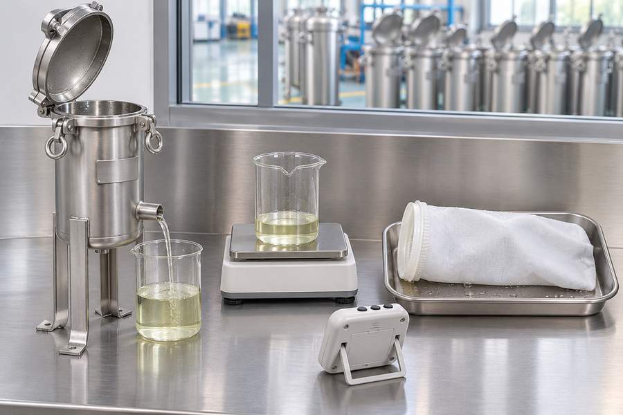
A longer drain time may recover more product but delay the next batch. Compare the added recovery with the extra downtime before specifying a slower operating sequence.
For example, a trial collecting 3 kilograms of liquid at a measured density of 1.2 kilograms per liter recovers 2.5 liters. These are illustrative values, not a housing specification.
That collected volume does not reveal the remaining inventory by itself. Measure accessible retained liquid separately under an approved procedure, or use a validated mass balance with clearly stated boundaries.
When discharge stops prematurely, investigate vent operation, pressure conditions, and possible restrictions. If liquid remains at the bottom, examine the relationship between the internal collection point and drain elevation.
Slow discharge may indicate high viscosity, restricted piping, insufficient pressure equalization, or unsuitable drainage geometry. Check these factors individually before deciding that the housing requires modification.
Liquid that returns after drainage may originate from connected piping or an isolation valve that does not provide the expected separation. Review the complete process arrangement before changing the housing.
Inspect the housing chamber and filter element separately. Liquid retained inside media, filter cake, or cartridge passages should not automatically be classified as liquid remaining in the vessel.
For a more objective assessment, use a controlled, timed gravimetric inventory. Collect and weigh drainage over a defined period, then use the measured liquid density to convert mass into volume.
Keep recovered good product and cleaning waste in separate records. Define the collection boundary, initial operating condition, drainage endpoint, and measurement period so that repeated assessments remain comparable.
What Should Buyers Consider When Selecting a Low-Residual-Liquid Filter Housing?
Specify the acceptable residual-liquid level or agreed drainage endpoint rather than requesting a completely dry housing without qualification. Identify whether the requirement applies to the vessel alone or includes filter elements and connected piping.
Review the proposed internal arrangement, drain locations, vent connections, and chamber configuration. Confirm that the equipment drawings reflect the intended installation orientation and actual piping interfaces.
Review the available liquid filter bags in relation to filtration requirements, media characteristics, and product handling. Element selection should consider both filtration performance and practical removal conditions.
Where drainage performance is critical, agree on a controlled trial protocol with the supplier before equipment acceptance. Define the process liquid, operating condition, initial inventory, isolation procedure, and timed drainage endpoint.
Record the collected liquid mass and apply the measured density for volume correction.
Document recovered good product separately from cleaning waste, and identify whether the reported result covers the housing, filter elements, or complete piping system.
Use the agreed results and drawing review to resolve any design changes before production approval. Never promise zero residual liquid or modify a pressure boundary in the field without proper engineering authorization.