
Filter cartridges collapse when differential pressure exceeds their structural resistance. Excessive flow resistance, clogged media, unsuitable materials, temperature changes, incorrect flow direction, and inadequate internal support can contribute to deformation.
Identifying the failure mechanism requires examining operating conditions and cartridge construction together. Engineers should distinguish mechanical overload from material degradation before selecting replacements or changing filtration procedures.
Reading the Loads That Deform a Cartridge
Subtract the pressure on the clean side of the element from the pressure on its feed side to establish the forward-flow differential. It represents the resistance encountered as fluid passes through the filter media.
As particles accumulate, the available flow paths become increasingly restricted. Maintaining the same flow rate may require a greater pressure difference, increasing the mechanical load on the cartridge.
Line pressure and differential pressure describe different operating conditions. Line pressure indicates the pressure within the system, whereas differential pressure measures the pressure drop across the cartridge.
A cartridge can therefore experience high line pressure without excessive differential pressure. Conversely, a substantial pressure difference across the element can cause deformation even when overall system pressure remains within acceptable limits.
Inward collapse occurs when pressure outside the cartridge exceeds pressure inside it. This condition creates an inward mechanical load that can compress unsupported media or damage the internal structure.
Outward deformation occurs when internal pressure exceeds external pressure sufficiently to overcome the cartridge’s structural resistance. Reverse-flow arrangements can create this condition in some filtration systems.
The expected pressure direction depends on cartridge design and installation. Many conventional cartridges use outside-in flow, while certain high-flow configurations operate inside-out.
Some Zonel Filtech ZHFV high-flow cartridges use a coreless inside-out construction. A missing central core is therefore not automatically evidence of a defective or incomplete cartridge.
Visible deformation does not necessarily mean the filter media itself has collapsed. Other failures include media rupture, seam separation, end-cap detachment, and damaged sealing surfaces.
Media rupture creates an opening through which contaminants can pass. Seam separation or end-cap failure can produce bypass leakage even when most of the cartridge retains its original shape.
Main Causes of Filter Cartridge Collapse
Heavy contaminant loading progressively restricts the media. Fine particles, sticky substances, and accumulated solids can accelerate pressure-drop increases, particularly when the process produces substantial solids concentrations.
High fluid viscosity can also increase flow resistance. Changes in temperature, fluid composition, or production conditions may alter viscosity and create pressure loads different from those anticipated during cartridge selection.
Excessive flow rates can increase differential pressure, especially when the available filtration area is insufficient for the required throughput. Selecting cartridges solely according to connection size may overlook this limitation.
Installing a cartridge in the wrong orientation can expose its media and support structure to unintended pressure loading. The resulting deformation depends on its construction and specified flow direction.
Reverse flow may occur during backwashing, cleaning, draining, or particular shutdown procedures. However, not every cartridge is suitable for these operating conditions or repeated pressure reversals.
Before introducing reverse flow, verify the manufacturer’s permitted operating direction and differential-pressure limits. A cartridge designed for one-way filtration should not automatically be assumed suitable for backwashing.
Internal support helps a cartridge retain its shape under pressure loading. Depending on the construction, this support may come from a center core, external cage, perforated components, or reinforced connections.
If the support structure lacks sufficient strength, filter media may buckle under differential pressure. Localized deformation can also develop around unsupported areas or mechanically weak connections.
End fittings also influence overall integrity. Weak bonding, incompatible connections, or inadequate attachment between components can cause separation when the cartridge experiences operating loads.
Temperature and chemical exposure can change the mechanical properties of filter media and structural components. Certain polymers soften at elevated temperatures, reducing their ability to withstand pressure loading.
Incompatible chemicals may cause swelling, embrittlement, or deterioration. Adhesives, seals, and end-cap materials can also degrade, potentially weakening connections before visible media damage occurs.
Cleaning agents deserve particular attention when cartridges undergo repeated cleaning cycles. Include the cleaning exposure in the compatibility review: a short hot wash can stress materials differently from hours of normal filtration.
Incorrect seating, unsuitable dimensions, and improperly secured connections can create uneven mechanical loading. Missing support components or damaged seals may also interfere with the intended flow arrangement.
Cartridges with similar external dimensions may have different internal structures and pressure limitations. Confirm the exact model, connection arrangement, and operating requirements before installing replacements.
How to Diagnose a Collapsed Filter Cartridge
Retain the failed element and its packaging identification until the investigation is complete. Photograph both ends and the full length before cutting or cleaning away evidence of the failure.
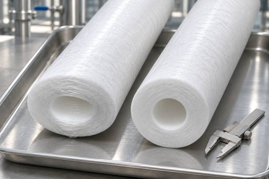
Check where the pressure instruments are connected. Readings across a complete skid can include losses in piping and valves; they may not represent the pressure difference across the cartridge alone.
Compare the instruments under the same stable conditions and check their calibration. A blocked sensing line or mismatched gauge range can conceal an increasing load on the element.
Review the recording interval as well as the peak shown on the trend. A slow logging system may miss a brief pressure reversal during pump stopping or valve movement.
Do not raise a changeout alarm simply to extend a run. Separate the normal replacement threshold from the maximum structural rating, following the supplier’s temperature-dependent limits and plant operating procedure.
Remove the element only after the approved shutdown sequence has established safe isolation, released trapped pressure, and controlled any hot or hazardous liquid.
Record its installed orientation before removal so the deformation pattern can be interpreted correctly.
Check whether the element has collapsed inward, expanded outward, or developed localized distortion. Inspect the media, center core, external support, seams, end caps, and sealing surfaces.
Look for uneven contaminant accumulation, discoloration, swelling, and brittle areas. These observations can help distinguish mechanical overload from chemical degradation or abnormal filtration conditions.
Examine inlet pressure, outlet pressure, and differential-pressure records around the time of failure. Compare actual operating conditions with the cartridge’s specified mechanical limits.
Determine whether pressure increased gradually as contaminants accumulated or changed suddenly during equipment operation. Gradual increases may indicate clogging, while sudden changes warrant investigation of transient conditions.
Inspect the housing for blocked passages, damaged internal components, and restrictions around cartridge connections. Verify that the installed element matches the housing’s dimensions and connection requirements.
| Failure indication | Possible cause | Recommended check |
| Inward deformation | Excessive differential pressure | Pressure records and contaminant loading |
| Localized buckling | Insufficient structural support | Core, cage, and media construction |
| Swelling or softening | Material incompatibility | Fluid and temperature exposure |
| Damaged end connections | Installation or bonding problems | End fittings and housing compatibility |
| Sudden deformation | Pressure transients | Startup, shutdown, and valve records |
How to Prevent Filter Cartridge Collapse
Monitor differential pressure during operation and investigate abnormal increases before deformation occurs. Replacement criteria should follow the applicable cartridge specifications and actual process requirements.
Do not apply one universal changeout limit to every cartridge. Different media structures, filtration areas, support arrangements, and operating conditions produce different allowable differential-pressure limits.
Check the manufacturer’s maximum differential-pressure rating at the actual operating temperature. Where available, obtain the hot differential-pressure rating rather than relying exclusively on a room-temperature specification.
Use the correct cartridge dimensions and connection arrangement. Follow installation instructions carefully, ensuring that the element seats properly without damaging its end fittings or sealing surfaces.
When repeated collapse occurs, investigate the original cause before installing another element. Replacing cartridges without correcting excessive loading or unsuitable operating conditions may reproduce the same failure.
Specify a Replacement That Matches the Recorded Service Conditions
Understanding different liquid filter cartridge constructions helps buyers evaluate media strength, internal support, and flow arrangements for specific applications.
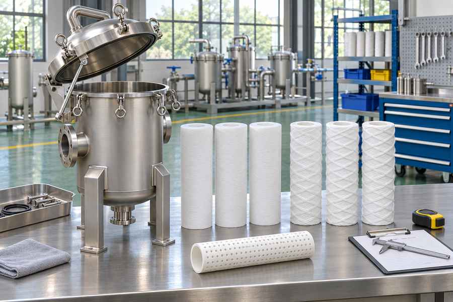
Compatibility with cartridge filter housings also matters because cartridge dimensions, connections, and operating conditions determine how pressure loads transfer through the assembly.
- Pressure conditions: Specify normal and maximum line pressure, expected differential pressure, and potential pressure fluctuations.
- Flow requirements: Provide normal and peak flow rates, fluid viscosity, and intended flow direction.
- Fluid characteristics: Identify chemical composition, operating temperature, contaminant type, and approximate solids loading.
- Filtration requirements: Confirm the required filtration rating, cartridge dimensions, and expected service conditions.
Ask whether the proposed element uses a supported or coreless configuration and how its construction accommodates the intended pressure direction. Neither arrangement should be judged without considering its complete design.
Request the manufacturer’s maximum differential-pressure rating and the temperature at which it applies. Confirm whether the stated limit covers the intended flow direction and operating conditions.
Clarify whether reverse flow or cleaning procedures are permitted. Verify material compatibility, end-fitting dimensions, sealing requirements, and any restrictions on pressure fluctuations.
For a plant trial, agree on the cartridge configuration, installation requirements, operating limits, and monitoring points with the supplier.
Record initial inlet and outlet pressures, flow rate, and temperature, then track differential-pressure development throughout the trial.
Evaluate the trial against the agreed filtration requirements and manufacturer’s limits. This provides a practical basis for approving the replacement design without assuming that dimensional compatibility alone guarantees mechanical suitability.