
A liquid filter that works in a short trial can still become the limiting step when production expands. Larger batches expose the element to more contamination, longer operating periods reveal compatibility problems, and higher flow changes the pressure requirement. Before committing to a production installation, test the filter as part of the process it will actually serve.
The seven tests below cover removal performance, hydraulics, capacity, compatibility, sealing, operating transitions, and changeout recovery. Each should have a written acceptance criterion. The purpose is to identify the operating envelope that has been demonstrated, including the conditions that still need investigation.
Define the trial before collecting results
State the required filtrate quality, normal and maximum flow, liquid temperature range, batch size, and expected feed variation. Identify the proposed medium, dimensions, seals, housing, and connections. If any of these change during the trial, preserve the original result and mark the new configuration separately.
Use representative feed. A sample collected after solids have settled may be easier to filter than the mixed liquid delivered during production. A clean laboratory liquid can establish a hydraulic reference but cannot establish service life in a contaminated process. Document how the sample was collected and stored.
Define stopping criteria before starting. These include the applicable differential pressure, equipment limits, quality limits, and the intended duration or processed quantity. A successful trial is not one that simply avoids an obvious failure. It is one that meets the stated requirements within a clearly recorded set of conditions.
Plan measurement quality as carefully as equipment selection. Check instrument suitability, sampling methods, units, and recording intervals. If the trial cannot distinguish a real change from measurement noise, its apparent precision will not make the scale-up decision more reliable.
1. Test particle removal against the product requirement
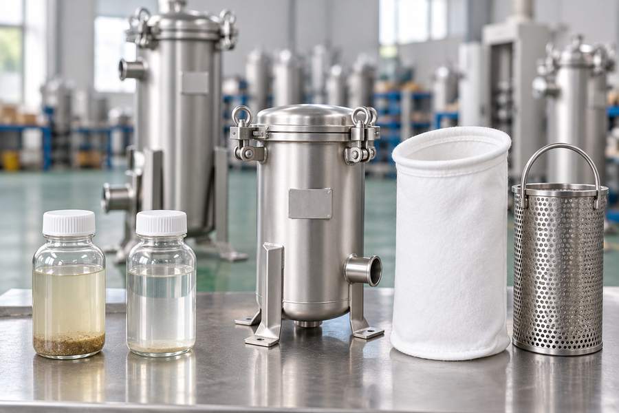
Measure what matters to the downstream process. This may be a particle count within a relevant size range, visible defects, a solids measurement, or another validated product test. Turbidity can be useful in some liquids, but it is not automatically a substitute for particle size or a direct measure of the contamination that causes the problem.
Collect upstream and downstream samples under matched conditions. Note when the samples were taken, the flow at the time, and whether a transfer or mixing event was occurring. Follow the sampling method for flushing connections, selecting containers, and preventing outside contamination.
Collect filtrate samples at several defined stages of the production run. Startup, stable operation, and operation near the approved end point can behave differently. If the line restarts after a pause, include that event in the sampling plan. A single good downstream sample cannot establish performance across a complete batch.
Compare the result with the actual acceptance criterion, not only with the supplier’s micron label. If a particle-count method is used, identify the size threshold and efficiency calculation. Keep the raw upstream and downstream results so that a low upstream count is not mistaken for an especially demanding challenge.
What a useful result looks like
The report identifies the feed condition, method, sampling locations, measured values, and acceptance decision. It also explains any limitation, such as insufficient contamination to challenge the filter at the critical size. An inconclusive challenge should remain inconclusive rather than being recorded as a pass.
2. Measure flow and clean differential pressure
Install a fresh, correctly seated element and establish a stable clean baseline. Record inlet and outlet pressures, actual flow, and liquid temperature together. Identify the components between the pressure connections so that housing and pipe losses are not confused with the medium alone.
Test a practical range of approved operating rates. The production target should fall within the demonstrated range rather than beyond the last measured point. Include the cold or otherwise difficult condition when viscosity is expected to matter. Water results should be labeled as water results if the production fluid behaves differently.
Check whether the downstream equipment receives the required pressure at the intended flow. A filter can appear acceptable in isolation while consuming too much of the pressure available to the rest of the line. Include relevant valves, connections, and pipework when evaluating the installed arrangement.
The trial should also identify the margin between clean operation and the approved replacement point. A system that starts close to that point may have little practical room for loading. Increasing pump pressure is not an automatic remedy; the entire equipment and process envelope must remain acceptable.
When reviewing a stainless steel filter housing, use data for the proposed configuration. Different connections, internal arrangements, and element counts can change the result. The largest advertised flow is not a substitute for a pressure-flow assessment at the actual duty.
3. Measure capacity with the real contaminant
Continue the trial long enough to observe loading behavior, or clearly state that capacity has not been established. Track differential pressure against processed quantity, with time and operating conditions retained alongside it. This makes comparisons more meaningful when production rates change.
Record the reason the test ends. Reaching a quality limit is different from reaching a pressure limit, exhausting the available feed, or stopping because the shift ends. Do not report the quantity processed before an arbitrary stop as the element’s full capacity.
Inspect the used element after safe removal. Note whether the deposit is distributed evenly, concentrated in a limited region, or associated with soft material that blocks the medium. Photographs and representative samples can help explain the pressure trend, but visual inspection does not replace the quality measurements.
Where feed conditions vary, test the conditions likely to govern production. A filter that completes a clean batch may fail to complete a batch made from a different raw material source. Keep capacity results associated with their feed conditions rather than averaging away the variation.
Laboratory challenge data can help compare candidates, but do not assume a standard test dust behaves like the plant’s contaminant. Particle shape, deformability, and interactions with the liquid can change loading. The production trial is the place to confirm how those factors affect the proposed element.
4. Check compatibility over realistic exposure
Review all wetted materials: medium, core or basket, end caps, adhesives where present, seals, housing, and any recovery components. Include the production liquid and cleaning agents at their relevant concentrations and temperatures. Compatibility with the main liquid alone is not enough if cleaning is more demanding.
Use supplier information to define a suitable candidate, then validate the aspects that matter to the application. An exposure test may examine changes in dimensions, stiffness, mass, appearance, or filtrate quality. The method should be chosen for the suspected failure mechanism rather than using a short soak as universal proof of suitability.
Consider the full operating cycle. A material may see temperature changes, repeated wetting, or cleaning between batches. Those exposures can differ from steady operation. Base the exposure test on the cycling frequency and intensity expected in service, and identify any operating conditions the trial has not covered.
Check product contact requirements separately from chemical resistance. A component can remain mechanically intact yet release substances or fibers that are unacceptable in the process. Ask for the documentation relevant to the intended use and verify the finished assembly, rather than relying on a general material description.
For liquid filter cartridges, include the selected construction and end connection in this review. Material names alone do not describe every component of a finished cartridge. Keep the exact candidate identification with the test record.
5. Verify seal fit and control of bypass
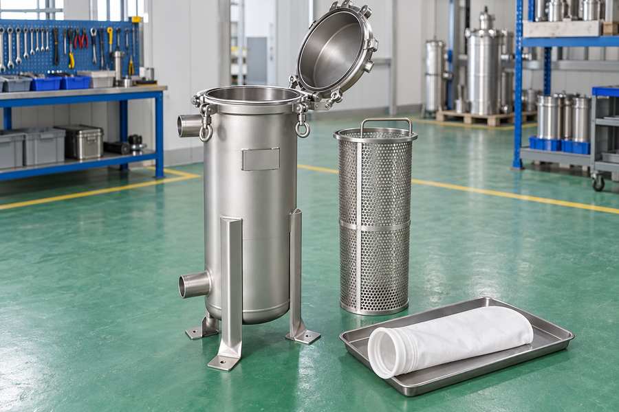
Confirm that the element fits the housing as intended. For bags, inspect the collar or ring, seat, retaining arrangement, and support basket. For cartridges, verify length, end connection, gasket or O-ring arrangement, and the specified seating method. A part that can be placed inside the vessel is not necessarily a qualified replacement.
Inspect the assembly before testing and after the run. Look for uneven compression, displaced seals, damaged support, or evidence that liquid could have avoided the medium. Use the housing supplier’s approved checks; do not invent a pressure or integrity test for equipment that was not designed for it.
Pair this inspection with the removal results. An unexpectedly low differential together with poor filtrate quality may point to bypass or damage, although it does not prove either. Investigate the assembly before deciding that the selected micron rating is too coarse.
Record the installation steps and any tools or retainers required. If the trial succeeds only when one specialist adjusts the element in an undocumented way, the production method is not ready. The installation should be reproducible by trained operators following the approved procedure.
6. Test normal starts, stops, and changeovers
Production rarely consists of one uninterrupted steady run. Pumps start, valves change position, tanks empty, and batches pause. Include the transitions the filter will actually experience within the approved operating procedure, while monitoring pressure and downstream quality where relevant.
Observe how the system fills and vents, how flow stabilizes, and where startup liquid is directed. Air trapped in the arrangement or an inconsistent restart procedure can complicate the interpretation of the trial. Establish the correct sequence before comparing candidate elements.
Where the process uses a duty and standby arrangement, test the intended changeover under controlled conditions. Confirm that the available filtration path can maintain the required duty and that the transition does not deliver unacceptable liquid downstream. A diagram showing two vessels is not evidence of uninterrupted production.
Do not create abnormal pressure shocks to see what the equipment can tolerate. The test is intended to confirm approved operating behavior, not to discover destructive limits. If normal transitions produce unacceptable conditions, resolve the controls or layout before increasing production.
Record the liquid held during pauses and the conditions for restarting it. Products that settle, cure, or have hygiene limits may require a different procedure after a long stop. Define the tested pause duration and do not extend that result to an unlimited shutdown.
7. Measure changeout time and product recovery
Perform a complete representative changeout. Include isolation, depressurization, drainage, element removal, inspection, replacement, refilling, venting, and quality release. Record the total interruption as well as the hands-on replacement time. The latter can be a small part of the actual production loss.
Measure retained liquid and its destination. Separate accepted recovered product from waste, cleaning liquid, and startup diversion. A larger filter may extend the run while increasing the amount held at each stop, so both frequency and loss per event belong in the comparison.
Check access in the proposed installation. The pilot unit may have open space around it that the final location does not. Verify room for lid movement, bag or cartridge withdrawal, lifting equipment where needed, and safe placement of wet components and recovery containers.
Include the correct consumables and spare parts in the exercise. A replacement procedure that assumes a seal is always reusable should be checked against the equipment requirements and its observed condition. Use difficulties encountered during the exercise to revise the production spare-parts list, especially where a missing or unsuitable component delayed replacement.
Translate the results into a production specification
Scaling flow by element count is only an initial estimate. The full installation can have different distribution, connection losses, hold-up, and maintenance constraints. Use the pilot results to establish the required duty per effective area, then have the proposed production arrangement checked against that duty.
Preserve the conditions behind each result. Specify the liquid, temperature range, feed variation, retention requirement, flow, clean differential, stopping criteria, and demonstrated processed quantity. Separate measured results from calculated estimates and from supplier statements that still need confirmation.
List unresolved issues explicitly. A short test may establish clean hydraulics and installation fit without establishing long-term compatibility or capacity. That is useful progress if the remaining work is visible. It becomes misleading only when a partial trial is presented as complete qualification.
Finish with an acceptance record that production, maintenance, and quality can all use. The chosen filter should have a clear operating envelope, a repeatable installation and changeout method, and a monitoring plan. Those details make a successful pilot transferable to the plant instead of leaving the result dependent on the conditions of one carefully managed test.