
Adding a bag filter to an existing liquid process line involves more than finding space for a housing and matching the pipe connection. The filter changes the pressure requirement, introduces retained liquid, and creates a maintenance task that the original line may not have been designed to support. A successful retrofit defines those changes before installation.
Start with the filtration objective and the actual operating conditions. Then check the hydraulic allowance, equipment materials, connection details, support, isolation, drainage, and access. Commission the finished installation against a recorded baseline so that operators can recognize normal loading and distinguish it from a problem elsewhere in the line.
Write down the job the filter must perform
Identify the contamination that needs removal and the consequence it causes. Is the objective to protect a pump or nozzle, reduce visible defects, remove transfer debris, or meet a downstream particle requirement? These duties can lead to different media and retention specifications even when the process liquid is the same.
Define the accepted filtrate using a relevant test. A micron label alone does not state every aspect of performance. Where removal efficiency matters, obtain the test basis and compare it with the particle sizes relevant to the process. Do not assume that a nominal rating from one product equals an absolute rating from another.
Record normal flow, peak flow, batch volume, liquid composition, temperature range, and expected contaminant variation. Include startup and cleaning conditions. The highest operating temperature or most aggressive liquid may occur outside normal production, and the filter assembly still has to be suitable for those conditions.
Decide how long the filter should run before maintenance. A housing that reaches the required flow with a clean bag may still be impractical if it cannot complete the intended batch. Use representative loading information or a pilot trial to connect flow capability with a realistic replacement interval.
Survey the installed line before selecting the location
Walk the actual route with the current drawing. Confirm pump location, valve positions, flow direction, elevations, connection types, nearby equipment, and available space. Mark any differences between the drawing and the installation so they do not carry into the retrofit design.
Choose a location where the filter can perform its intended role. A filter placed before the source of the unwanted debris cannot remove that debris from the downstream product. A filter installed far from the equipment it protects may leave intervening pipework as another contamination source.
Review whether the proposed location is on pump suction or discharge. A suction-side restriction can affect the pump’s inlet conditions and needs a specific assessment. Do not move a filter onto the suction line merely because that location has more floor space. Have the hydraulic consequences checked for the actual pump and liquid.
Look beyond the footprint. Operators need room to open the lid, withdraw the bag and support basket, inspect the seal, and move the wet element to a suitable container. Overhead pipework or a low platform can make a physically installable housing difficult to service.
Check the maintenance route
Follow the route a used bag will take from the housing to its container. Avoid arrangements that require carrying dripping material over electrical equipment, walkways, or clean components. Provide a suitable place for replacement parts and inspection tools close enough to support the approved procedure.
Consider how recovery and cleaning vessels will be positioned. A drain is of little practical use if its outlet cannot be connected to the intended destination. Small layout details often determine whether operators can follow the procedure consistently once the line is busy.
Calculate the pressure the new assembly will consume
Establish the existing flow and pressure conditions before the change. Measure at useful locations and record liquid temperature. If the current line already struggles to meet demand, adding filtration without addressing the hydraulic limitation may reduce output further.
Evaluate the proposed housing, bag, valves, fittings, and connecting pipework together. The total loss is not limited to the medium. A restrictive connection or a series of tight bends can consume pressure even with a clean bag. Use relevant supplier information and engineering calculations for the actual liquid and flow.
Check clean and loaded operation. The pump must support the required duty while the filter approaches its approved replacement condition, with sufficient pressure remaining downstream. Keep the assessment within the limits of the pump, housing, element, seals, and process equipment.
Temperature deserves explicit attention. A liquid that becomes more viscous when cold may create its highest starting resistance at the beginning of a shift. A water-based catalog curve should not be applied unchanged to a different fluid without a justified correction or trial.
Do not treat a larger pump as the default solution. More pressure can introduce other consequences and does not correct a poor media choice or an unnecessarily restrictive installation. First determine which part of the arrangement is consuming the allowance.
Match the bag, housing, and wetted materials
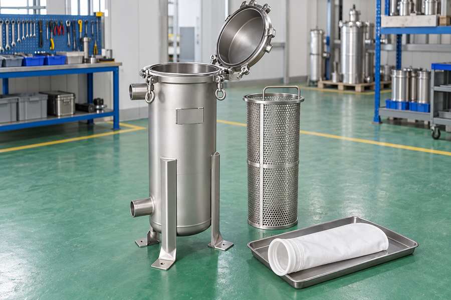
Select the liquid filter bag construction for retention, liquid compatibility, contaminant behavior, and the intended service interval. Include the bag ring or collar and the required support arrangement. The medium is only one part of the sealing and mechanical system.
Confirm the fit with the proposed housing. Bag length, diameter, collar design, retaining mechanism, and basket all matter. A visually similar replacement may not seal correctly. Keep an approved part specification so purchasing and maintenance do not have to rely on a broad description such as standard bag.
Review housing and seal materials against both production and cleaning exposure. Check each candidate material against the actual formulation, its concentration, the exposure temperature, and the time it will remain in contact with the liquid. Labels such as stainless steel or chemical resistant leave those application-specific compatibility questions unanswered.
Obtain the applicable pressure and temperature limits for the complete assembly. Assess the pressure contained by the vessel separately from the pressure difference acting on the filter bag. Use the documented operating envelope rather than assuming that a vessel pressure rating is also the allowable pressure difference across its element.
The proposed stainless steel bag filter housing should be specified with its actual connection standard, seal, support, and access requirements. Confirm the selected configuration with the supplier before finalizing fabrication or ordering connecting parts.
Provide proper pipe connections and independent support
Match the connection standard, nominal size, pressure class where applicable, and sealing method. Similar-looking threaded or flanged connections are not necessarily compatible. Verify the dimensions and specification instead of relying on a tape measurement alone.
Support the housing and pipework according to the design. The vessel should not become an unintended support for the surrounding line, and the line should not force misalignment into the vessel connections. Account for the loads associated with a filled housing and with maintenance operations.
Review thermal movement and vibration where relevant. A retrofit inserted into an existing run can change how loads are transmitted. The arrangement may need suitable supports or flexibility, but those provisions should be engineered for the actual service rather than improvised during installation.
Keep the flow path practical and inspectable. Where contamination control matters, assess dead spaces and the ability to drain or clean connecting branches. Leave enough pipe length and clearance for operators to reach the isolation valves, empty the drain, and operate the housing closure.
Design isolation, venting, and drainage before the shutdown
The housing must be capable of safe maintenance without relying on an operator loosening a fitting to release pressure. Provide the approved isolation, venting, drainage, and verification arrangements for the equipment and process. Consider pressure that can enter from either side.
Route drains and vents to suitable destinations. The destination depends on the liquid and whether the stream is recoverable product, contaminated upstream liquid, cleaning fluid, or waste. Do not connect streams simply because a nearby drain is convenient.
A bypass requires a clear process decision. If unfiltered liquid is not acceptable downstream, a bypass cannot be used to maintain production during a bag change. Alternatives may include a planned stop, suitable buffering, or an engineered duty and standby filtration arrangement.
Make valve identification and operating status clear. A retrofit can add branches that are unfamiliar to the existing operators. Update the drawing and procedure so the required state during production, maintenance, and restart is unambiguous.
Plan how the housing will fill and vent at startup. The sequence should follow the equipment documentation and the process requirements. Compare the two assemblies and their operating requirements before adapting a filling or venting sequence from an existing installation.
Install during a controlled maintenance window
Prepare the correct parts, tools, supports, and documentation before stopping production. Confirm that the equipment delivered matches the approved specification, including the bag, basket, seal, and connection details. Resolve discrepancies before opening the line.
Follow the plant’s isolation and work-control procedure. Protect exposed pipework and clean-side components from debris during fabrication and assembly. Installation work can introduce the very contamination the filter is intended to control, so cleanliness is part of commissioning.
Inspect the installed flow direction, support, closure access, and drain routing against the approved arrangement. Check that instruments can be read and serviced, and that valves can be operated without reaching through unsafe or inaccessible spaces.
Complete the required assembly and leak checks using the approved procedure. Do not invent a test pressure from the vessel’s nameplate or use an arbitrary compressed-gas test. The installation and test method must be appropriate for the complete system and its contents.
Document the final arrangement. Photographs can supplement the revised drawing, particularly for valve identification and maintenance clearance, but they should not replace the necessary equipment and operating information.
Commission the filter with a useful baseline
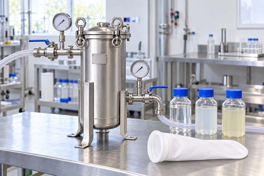
Install the approved bag and verify its seating and support. Fill, vent, and bring the line into operation according to the agreed procedure. Record the clean differential pressure, actual flow, temperature, and initial downstream quality once conditions are stable.
Observe the installation through a representative operating interval. Check for external leakage, unusual vibration, unstable pressure, or an unexpected reduction in flow. Investigate abnormalities before treating the installation as ready for unrestricted production.
Sample the liquid using the method chosen for the filtration objective. Confirm that the filter improves the relevant quality measure without creating a new problem. A lower particle count at one size does not automatically establish every product requirement.
Complete a representative bag change before closing the project. This checks whether the isolation, drainage, access, parts, and restart procedure work in the real location. Record retained product and maintenance duration so future planning uses actual experience.
Keep a short handover checklist
Before releasing the installation, confirm that the drawing matches the finished line, the approved element is identified, the clean baseline is recorded, and the maintenance sequence has been demonstrated. Assign responsibility for reviewing the first production runs so that early loading problems are not left to informal observation.
Include a record of the operating conditions that were not tested. If commissioning used a warm low-viscosity batch, a cold startup may still need validation. If only a small transfer was completed, full-batch capacity remains unproven. Make those boundaries visible to the people planning production.
Arrange a review after the first representative set of batches. Compare actual replacement frequency, quality results, and recovery with the original design assumptions. If performance differs, investigate the feed and installation data before changing the micron rating. This review helps close the gap between a mechanically completed retrofit and a filter that is working as intended in routine service.
Give operators a clear monitoring and replacement plan
State what to record and what action follows each limit. Differential pressure should be interpreted with flow and temperature, while quality results remain a separate requirement. The monitoring plan should also identify quality failures or other warning signs that call for inspection despite an ordinary pressure reading.
Keep an approved replacement specification and a practical spare-parts list. Include seals and other items that may be needed during a changeout, not only the bag. An installation that depends on an unavailable gasket can create avoidable downtime.
Review the baseline after a formulation change, a throughput increase, or a modification upstream. The original filter selection was based on a particular duty. A later change may alter capacity, viscosity, or contamination even if the vessel itself has not changed.
A bag filter retrofit is complete when the line delivers the required accepted output and operators can maintain it through a repeatable procedure. The housing is the visible addition, but the pressure assessment, sampling method, drainage route, and operating record are what make that addition useful in daily production.