
Choose an RO pretreatment cartridge by starting with the membrane supplier’s feed requirements, the actual water entering the cartridge housing, and the maximum flow the assembly must handle. Then verify the cartridge’s retention efficiency, materials, sealing arrangement, pressure limits, and replacement procedure. A micron number alone is not a complete specification.
The cartridge normally provides a final particulate barrier after the main pretreatment equipment. It should intercept particles that escape or originate upstream before they reach sensitive downstream components. It cannot compensate indefinitely for an overloaded or malfunctioning pretreatment train, and it does not solve dissolved-salt, scaling, or disinfectant problems merely because a finer grade is installed.
First decide what the cartridge must protect against
Map the water path from its source to the RO feed pump. Include storage, media filters, softeners where used, carbon treatment where used, dosing points, pipework, and the cartridge assembly. Each step can change the water or introduce a different operational risk.
Look for the particles that can realistically reach the final cartridge. They may include incoming sediment, corrosion debris, media fines, or solids released after maintenance. The dominant load during normal operation may be different from the load after backwashing or a tank disturbance.
Collect data at the cartridge inlet, not only from the original source water. A source-water analysis cannot show whether an upstream vessel is releasing fines. Conversely, a clean raw-water sample does not establish that the distribution pipework stays clean during startup.
State the downstream acceptance criteria with the RO supplier and the plant’s water-quality team. Include the relevant particulate and fouling indicators, permitted operating conditions, and required monitoring. The cartridge should be selected as one part of that treatment strategy.
Use the membrane guidance to establish a starting grade
DuPont’s FilmTec cartridge microfiltration guidance recommends a five-micron absolute cartridge as a general pretreatment choice and discusses tighter filtration for particular fouling risks. That guidance is a useful reference point for the applicable membrane system, not permission to select every RO cartridge from one number. Confirm the current requirements for the installed membrane and the site’s water conditions.
Specify what the rating means. A nominal five-micron element is not automatically equivalent to an absolute five-micron element. Ask for the retention efficiency, the test method, and the conditions supporting the supplier’s claim. The word “absolute” should lead to documentation rather than end the technical discussion.
A tighter grade may be appropriate where the agreed protection requirement demands it, but it can also increase resistance and replacement frequency. Before changing the grade, establish whether the suspected foulant is actually removable by that cartridge and whether the upstream process should address it more effectively.
A coarser grade may make differential pressure look better while weakening the final barrier. Do not treat a longer run as proof of better operation unless the downstream quality and protection requirements remain satisfied.
Separate suspended solids from the problems a cartridge cannot fix
Particulate filtration removes suspended material within its demonstrated performance envelope. It does not desalinate water. A conventional sediment cartridge also should not be assumed to remove dissolved hardness, dissolved silica, or a disinfectant simply because these substances matter to membrane operation.
Scaling control, chemical compatibility with the membrane, and biological management require their own validated treatment and monitoring measures. If those controls fail, changing the cartridge specification may distract from the actual cause of declining RO performance.
Colloidal behaviour needs particular care. A cartridge rating does not by itself predict the fouling potential of every water. Evaluate the water using the indicators and methods required for the system, and assess the complete pretreatment train when those indicators deteriorate.
When an RO problem appears, review the cartridge data alongside upstream performance and normalized membrane operating data where available. Avoid attributing every increase in membrane differential pressure to the cartridge or assuming a clean-looking element proves that feedwater conditions are acceptable.
Choose a construction with documented performance
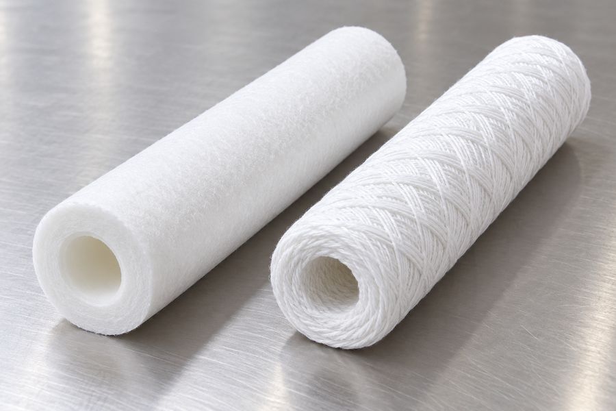
Melt blown, wound, and pleated cartridges may be considered for different pretreatment duties, but the manufacturing category alone does not establish suitability. Compare the actual element’s efficiency, available area or depth capacity, compatibility, and mechanical limits.
A depth element may be useful for a variable suspended-solids load. A pleated design may offer a different balance of area and retention performance. Either choice needs supplier data and a representative trial. Do not assume that an element with more visible material necessarily gives better protection or a longer useful run.
Review the available liquid filter cartridges with a defined specification in hand. Request the proposed product’s material details, rating basis, dimensions, end configuration, and recommended operating range. Use those details to assess how each proposed element would function in the specified RO feed line.
Where the cartridge is a final safety barrier, consistency between deliveries matters. Record the approved product code and construction rather than purchasing an unrestricted equivalent by micron rating and length. Qualify substitutions before putting them into routine service.
Size the complete assembly for the demanding operating condition
Determine the maximum flow that will pass through the cartridge assembly during normal production and relevant operating sequences. Do not confuse RO permeate output with feed flow. The cartridge upstream of the membrane train handles the feed passing through its location, which must be established from the actual system design.
Use the cartridge manufacturer’s recommended flow and pressure data for the selected grade and length. Account for water temperature, housing losses, and the number of elements. A housing connection large enough for the pipe does not prove that the installed cartridges provide adequate capacity.
Check the clean differential pressure at the design condition and reserve a practical loading allowance. The system needs to maintain the required supply to the downstream pump as the elements load. The equipment designer should confirm the available pressure margin and any low-pressure protection requirements.
Increasing the number of elements may reduce the duty on each one, but the internal arrangement must distribute flow effectively. Missing cartridges or unsuitable blanking arrangements can create an unfiltered path. Follow the housing manufacturer’s configuration requirements rather than improvising around an incomplete element set.
Use illustrative arithmetic carefully
Suppose an approved design basis calls for 24 cubic metres per hour through a vessel containing 12 identical cartridges. An even distribution would average two cubic metres per hour per cartridge. This is only a flow allocation example; it is not a recommended cartridge loading or proof that the vessel distributes flow evenly.
The supplier must confirm whether that duty is suitable for the exact element and conditions. A different length, grade, or water temperature can change the result. Use the calculation to organize the specification, then verify it against the product data and commissioning measurements.
Check all wetted materials and the mechanical fit
List the normal feed chemistry, temperature range, cleaning exposures, and any sanitizing procedure affecting the cartridge assembly. Check the media, support core, end caps, seals, and housing materials against those conditions. Compatibility information for one component does not qualify the entire assembly.
Confirm the exact cartridge length and end style. A double-open-ended element, a cartridge with an O-ring connection, and another proprietary fitting may require different supports or sealing arrangements. An element that can be physically placed inside the vessel may still fail to seal properly.
During installation, inspect the seating surfaces and the components that apply the specified compression or engagement. Follow the assembly procedure for the housing. Excessive force is not a remedy for the wrong cartridge dimensions or a damaged sealing surface.
The cartridge filter housing design should be reviewed together with the selected element. Check whether the assembly suits the required pressure, provides usable instrument ports, can be vented and drained, and leaves room for cartridge replacement.
Set replacement triggers before commissioning
Differential pressure is a useful operating signal, but it is not a complete measure of cartridge condition. Establish the allowed changeout threshold from the cartridge, housing, and process requirements. Temperature-dependent element limits and the downstream pressure requirement may constrain the permitted loading.
Also establish a maximum service interval appropriate to the system and supplier guidance. An element can spend a long time in low-solids water without developing a large pressure drop. Retain the scheduled servicing and hygiene controls even when the element shows little hydraulic resistance.
Unexpected downstream contamination, damaged elements, or an upstream upset may require action before the routine pressure threshold. Define these exceptions so operators are not forced to choose between a written pressure rule and evidence that the barrier may be compromised.
Record both inlet and outlet pressure, flow, and water temperature when evaluating a change. Comparing differential pressure at different flow rates can create a false impression of loading. A pressure reading that falls because the pump delivers less flow is not evidence that the cartridge has recovered.
Use short cartridge life as a diagnostic signal
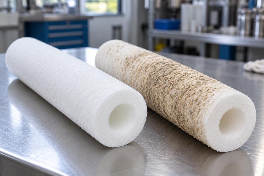
Frequent replacement deserves investigation upstream. Review media-filter performance, backwash and rinse procedures, tank conditions, and any maintenance immediately before the problem began. Identify whether the loading is persistent or associated with particular operating events.
Inspect a safely removed cartridge and obtain appropriate analysis of the deposit when needed. The deposit’s appearance can guide the investigation, but its composition needs to be established by an appropriate analytical method. Keep the analysis linked to operating records and representative water samples.
Do not automatically select a coarser element to reduce replacement frequency. That can move the burden downstream. Nor should every short run lead to a finer element: a tighter barrier may load even faster while leaving the upstream cause untouched.
If the cartridge is consistently doing the bulk solids-removal work, reconsider the pretreatment arrangement. Improve the stage intended to carry that load or evaluate a suitable additional treatment step. Then recheck the final cartridge duty after the upstream change.
Commission with measurements that operators can repeat
Before starting the RO, verify that all installed cartridges match the approved specification and are correctly seated. Check that the housing is clean and that any required flushing is completed through the designated route. Keep commissioning water out of production until the agreed acceptance conditions are met.
After completing the approved startup procedure, measure the performance of the freshly installed cartridge set as the reference for later readings. Record the cartridge batch, installation date, flow, temperature, pressures, and relevant feedwater measurements. These values give the next shift a practical reference for interpreting changes.
- Normal operation: Confirm the required flow and acceptable pressure margin with stable upstream treatment.
- Routine transitions: Check the water condition after backwash, restart, and other expected operating changes.
- Instrument response: Verify that pressure indications and applicable alarms behave as intended.
- Quality verification: Use the agreed sampling points and test methods to assess the water entering the RO.
- Maintenance rehearsal: Confirm isolation, depressurization, drainage, element access, and controlled restart under the site procedure.
A commissioning record should distinguish measured values from supplier estimates. If a difficult operating condition has not yet occurred, record that limitation and define how it will be assessed when representative water becomes available.
Keep spare elements ready for an upstream upset
Stock enough approved cartridges to respond to an unexpected loading event without substituting an unqualified grade. Store them in their protective packaging under the supplier’s recommended conditions, and inspect the packaging before installation. A spare element exposed to dirt or damaged during storage can undermine an otherwise careful replacement procedure.
Include the required seals and any specified installation components in the maintenance plan. If a damaged seal is discovered during a changeout, production pressure should not become a reason to reuse it or improvise a fit.
Give purchasing and maintenance the same specification
| Specification item | What to record |
| Protection objective | Applicable membrane requirements and water-quality acceptance criteria |
| Retention | Micron rating, efficiency, and supporting test basis |
| Materials | Media, core, end components, and seals |
| Fit | Length, diameter, end configuration, and housing compatibility |
| Operating envelope | Flow, temperature, pressure, and chemical exposure |
| Replacement | Differential pressure trigger, service interval, and exception criteria |
| Traceability | Approved product code, supply batch, and installation record |
This information prevents a common purchasing shortcut: ordering any cartridge that appears to have the right dimensions and micron number. It also gives maintenance staff a reason to question a replacement that looks different from the qualified product.
Keep a record of each changeout and its cause. Review accepted operating time alongside feed conditions, upstream events, and RO performance. The aim is a stable final barrier with predictable service, supported by upstream treatment that carries its intended load.
A well-chosen cartridge is therefore more than a fine filter in front of a membrane. It is a documented element and housing combination, operating within a known envelope, with measurable acceptance criteria and a clear replacement procedure. That is the basis for protecting the RO consistently as water conditions change.