
Filter housing corrosion occurs when process chemistry and service conditions damage protective metal surfaces, allowing degradation to develop through chemical attack, electrochemical reactions, or localized corrosion.
Chlorides, stagnant deposits, unsuitable cleaning agents, fabrication defects, and mechanical damage can accelerate deterioration, making material compatibility and operating conditions essential considerations when investigating damage or specifying replacement equipment.
Chemical Exposure and Process Fluid Incompatibility
Acids, alkalis, salts, and reactive compounds affect different metals in different ways. Corrosion severity depends on chemical composition, concentration, temperature, exposure duration, and the condition of the protective surface.
Fluid names alone are insufficient for material selection. Engineers should obtain relevant chemical concentrations, pH ranges, contaminants, and possible changes during production before specifying a housing material.
Process chemistry does not always remain constant throughout an operating cycle. Evaporation, dilution, chemical dosing, and changes in production conditions can alter concentrations and influence corrosion behavior.
Cleaning procedures introduce another potential source of chemical attack. Detergents, acidic cleaners, alkaline solutions, and disinfectants must be compatible with the housing material and its surface treatment.
Incomplete rinsing can leave chemical residues inside the vessel, particularly around connections, internal corners, and drainage points. These residues may create localized exposure even after production has stopped.
Moisture, Chlorides, and Environmental Exposure
Condensation forms when a metal surface becomes colder than the surrounding air’s dew point. Repeated condensation can keep housing surfaces damp, especially in humid production areas or temperature-controlled facilities.
Look behind brackets and around mounting contacts, where air movement is limited and water can remain against the shell. Moisture trapped beneath insulation or around structural connections may remain undetected during routine external inspections.
Include chloride exposure in the service review even when stainless steel is specified. Chloride-containing process water, cleaning solutions, and atmospheric deposits can undermine passive surface protection under susceptible conditions.
Grade 316L offers improved resistance to many chloride-containing environments compared with 304L, but it is not immune to chloride-induced corrosion. Actual suitability depends on concentration, temperature, exposure duration, and other environmental factors.
Water retained inside a housing creates different conditions from continuously flowing process fluid. Stagnation allows deposits to accumulate and may produce localized differences in oxygen concentration and solution chemistry.
Potential problem areas include vessel bottoms, internal corners, flange interfaces, and poorly drained sections. Deposits can also conceal corrosion, making surface inspection less reliable.
Electrochemical and Localized Corrosion Mechanisms
Galvanic corrosion occurs when dissimilar metals have electrical contact while exposed to an electrolyte. In that couple, attack is concentrated on the anodic member; the connected cathodic surface can increase the rate of metal loss.
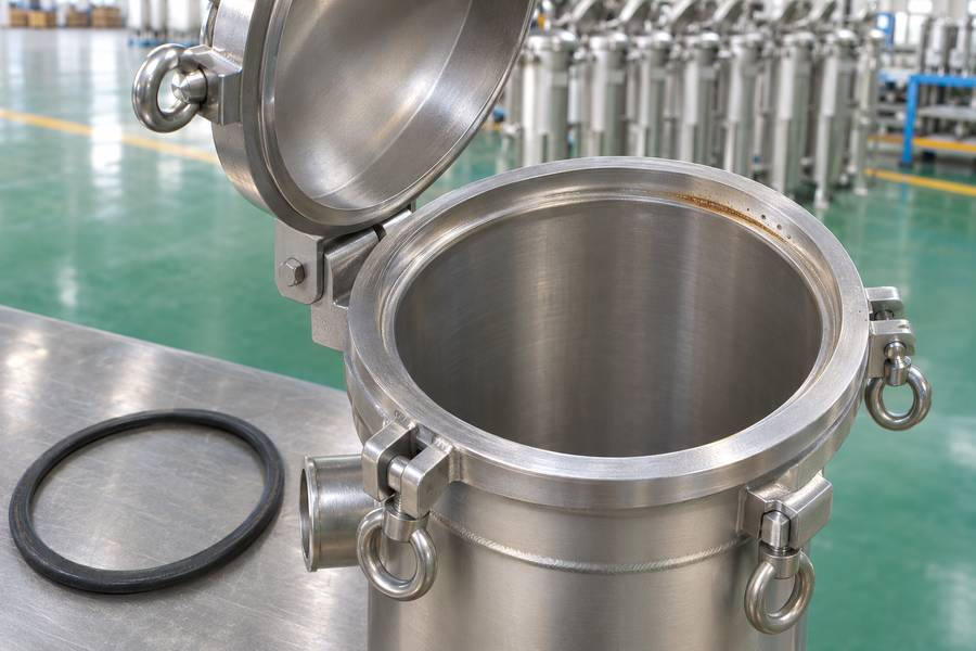
Review the metals used at each joint, including small fittings and fasteners that might differ from the shell specification. Suitable material combinations, electrical isolation where appropriate, and controlled exposure can reduce galvanic corrosion risks.
Pitting corrosion produces small, localized cavities that may penetrate deeply despite limited visible surface damage. It is particularly relevant when stainless steel encounters aggressive chloride-containing environments.
Inside a tight, wetted joint, oxygen supply and local chemistry can diverge from the bulk liquid and favor crevice attack.
Gasket interfaces, threaded connections, overlapping components, and deposits can create conditions favorable to localized chemical changes.
A stressed alloy can crack in an environment that promotes this particular failure mechanism, even without obvious general wall loss. The combination can produce cracks even when widespread surface corrosion is not obvious.
Cracks must not automatically be attributed to corrosion. Mechanical fatigue and other damage mechanisms can produce similar indications, requiring appropriate professional examination before determining the cause.
MIC describes corrosion affected by microorganisms and the local conditions they create, rather than a diagnosis established simply by finding bacteria. Biofilms can create localized chemical conditions that encourage corrosion beneath biological deposits.
Stagnant water, accumulated organic material, and suitable operating conditions may support microbial growth. However, discoloration or surface deposits alone cannot confirm MIC.
Temperature, Flow Velocity, and Mechanical Operating Conditions
Higher temperatures can accelerate chemical reactions and change the corrosion resistance of particular alloys. They may also increase the severity of localized attack in environments containing aggressive chemical species.
Material specifications should cover normal operating temperatures and foreseeable maximum conditions. Engineers should also consider cleaning temperatures because maintenance procedures may expose the housing to different thermal and chemical combinations.
Erosion-corrosion develops when fluid movement or suspended particles remove protective surface films while corrosive reactions attack the exposed metal. The combined action can cause faster material loss than either mechanism alone.
Inlets, outlets, bends, and flow restrictions are potential inspection locations. Local turbulence and particle impingement may create uneven damage patterns that differ from general chemical corrosion.
Pressure fluctuations and vibration are not direct chemical causes of corrosion, but they can contribute to mechanical fatigue and damage at connections, welds, and supporting structures.
Fabrication, Surface Treatment, and Assembly-Related Corrosion
Welding can produce heat tint and surface oxidation around weld seams. Untreated weld discoloration and the affected surface underneath can leave a locally vulnerable band beside otherwise sound stainless steel.
Handling and fabrication can introduce foreign particles onto metal surfaces. Embedded carbon steel particles, for example, may develop rust spots that resemble corrosion of the underlying stainless steel.
Transferred iron rust must be distinguished from actual vessel attack. Surface discoloration alone does not prove that the housing material has suffered measurable metal loss.
Fasteners and fittings made from incompatible metals can introduce galvanic corrosion risks. Gasket interfaces may also retain moisture or deposits, creating narrow spaces where crevice corrosion can develop.
Connection design should consider material compatibility, sealing performance, drainage, and inspection access. Damaged sealing surfaces and deteriorated gaskets require attention because leakage can create additional external corrosion exposure.
How to Diagnose and Prevent Filter Housing Corrosion
Photograph the surface before cleaning and mark the affected locations on a vessel sketch. Preserve representative deposits when an investigation requires laboratory analysis; cleaning first can remove useful evidence.
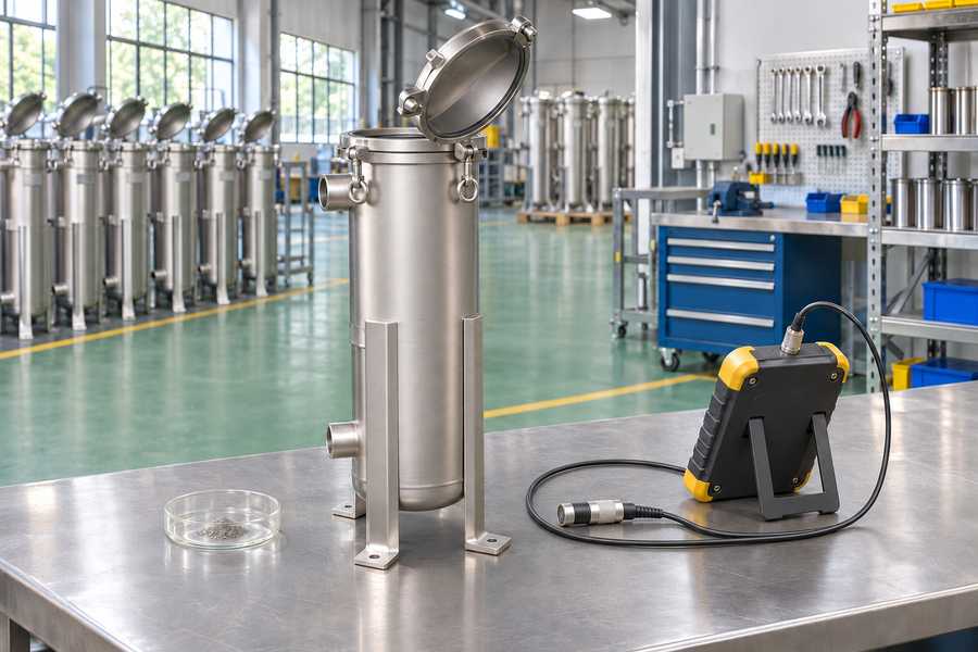
Build a timeline linking the first inspection finding with recent products, chemical additions, and sanitation work. A recent chemical substitution may explain a change that the normal operating specification misses.
For wall-thickness surveys, use repeatable measurement locations and an appropriate technique for the suspected damage. A few broad readings can miss narrow, deep pits between measurement points.
Replacement decisions need an engineering assessment of remaining integrity. A polished surface can look acceptable while pits or cracks still affect the pressure boundary beneath it.
After corrective work, establish a new inspection baseline and review it after a defined service interval. Recurrence at the same location may indicate unresolved chemistry, drainage, or fabrication conditions.
Choosing suitable stainless steel filter housings requires evaluating the process fluid, temperature, pressure, and cleaning procedures.
Review the liquid filter cartridge materials alongside the shell, because media, cores, and end fittings share exposure to the process.
Inspect the affected area, document its location, and compare the findings with process chemistry, operating history, and maintenance records. Use the visible damage pattern to decide which service records and component details to examine first.
| Visible condition | Possible mechanism | Recommended check |
| Widespread surface deterioration | General chemical or atmospheric corrosion | Review fluid chemistry and environmental exposure |
| Small pits or cavities | Pitting corrosion | Check chloride exposure and material grade |
| Damage around joints | Crevice corrosion or retained moisture | Inspect gasket interfaces and drainage |
| Rust near dissimilar metal fittings | Galvanic corrosion or transferred iron contamination | Check material combinations and surface condition |
| Cracks near stressed areas | Stress corrosion cracking or fatigue | Examine crack characteristics and operating stress |
| Damage near inlets and outlets | Erosion-corrosion | Review flow conditions and suspended particles |
Inspection should also identify pits, cracks, leakage, wall-thickness changes, and damage around welds. Suspected structural deterioration requires assessment by qualified personnel using appropriate inspection methods.
Before opening a filter housing, isolate it from the process, depressurize it completely, and follow the site’s approved safety procedures. Never rely solely on a pressure indication to establish safe conditions.
Material selection should begin with a documented description of the process environment. Obtain fluid composition, concentration ranges, pH, operating temperature, cleaning chemicals, and potential contaminants.
Evaluate the complete wetted assembly, including internal components, fasteners, fittings, and gaskets. A compatible housing body does not ensure reliable service if connected components introduce galvanic or chemical compatibility problems.
Inspection intervals should reflect process severity, operating history, material selection, and the consequences of equipment failure. Areas with previous corrosion, deposits, or leakage deserve particular attention.
- Surface inspection: Examine welds, joints, internal corners, drainage points, and areas beneath deposits for discoloration, pits, and cracking.
- Thickness monitoring: Use suitable inspection methods to evaluate wall loss and investigate unexpected changes against documented baseline measurements.
- Cleaning control: Remove deposits with procedures compatible with the housing material and avoid improvised chemical treatments.
- Operating records: Track process chemistry, temperature changes, cleaning procedures, and recurring leakage to identify changing exposure conditions.
- Corrective action: Address the underlying corrosion mechanism rather than repeatedly removing visible rust without investigating its source.
Do not attempt improvised acid mixtures to remove corrosion, particularly when the housing material and chemical compatibility are uncertain. Uncontrolled cleaning can cause additional damage or create hazardous reactions.
Ask the supplier to identify the housing material, wetted components, fasteners, gasket materials, weld treatment, and applicable surface finishing. Request material identification and supporting documentation appropriate to the application.